IoT - Creating an Arduino I²C slave device to use with Android Things
It is often interesting to use a microcontroller with Android Things when you need some peripherals that require to send/receive pulses at a really fast frequency, or simply if you are too lazy to create a driver for a given peripheral when you are prototype something quickly.
If you are using, for instance, a DHT11 humidity & temperature sensor module, which sends pulses from 26-28μs (data bit “0”) to 70μs (data bit “1”), you will notice that it won’t work with the current version of Android Things which has a GPIO frequency around 3kHz (~300μs pulse duration).
An easy way to bypass this issue is to use an Arduino and communicate between the Android Things board and the Arduino over either UART, USB, SPI, or other ways.
Today, we will exchange data between an Android Things board and an Arduino over I²C for 3 reasons:
- This way of communication is easy to understand / implement
- I²C only requires 3 wires (Data “SDA”, Clock “SCL”, and Ground “GND”)
- You can connect multiple slaves to the same bus, so if you are building your own custom board and are already using I²C components, you won’t need to add another interface to communicate with the MCU.
Building an I²C fan
We will build an Arduino-powered fan. Using I²C, the Android Things master device should be able to:
- Turn on / off the fan
- Set the fan speed (low / medium / high)
- Get the current fan speed value
Android Things I²C methods
Here’s a sum-up of all the I2cDevice methods provided by the Things Support Library.
With those, you can read or write data (either one byte, two bytes, or as many as you want, in a buffer).
| Data size | Using a register | Read method | Write method |
|---|---|---|---|
| 1 Byte | ☑ | readRegByte(int reg) |
writeRegByte(int reg, byte data) |
| 2 Bytes | ☑ | readRegWord(int reg) |
writeRegWord(int reg, short data) |
| Many Bytes | ☑ | readRegBuffer(int reg, byte[] buffer, int length) |
writeRegBuffer(int reg, byte[] buffer, int length) |
| Many Bytes | ☐ | read(byte[] buffer, int length) |
write(byte[] buffer, int length) |
Registers help understanding where you are reading from or writing to.
You can consider those as categories or actions. When you write some data to a register, it is easier to understand what will be impacted by this write operation.
In our project, we will use 2 different registers
REGISTER_POWER= 0x01REGISTER_SPEED= 0x02
Those 2 registers will be enough to perform the following actions:
| Action | Operation | Register | Data to write |
|---|---|---|---|
| Start the fan | Write | 0x01 | 1 |
| Stop the fan | Write | 0x01 | 0 |
| Set the fan speed | Write | 0x02 | 150 (low), 200 (medium), 250 (high) |
| Get the current speed | Read | 0x02 |
So the writeRegByte(0x01, 1.toByte()) call in our Android Things project will turn on the fan, while the writeRegByte(0x02, 150.toByte()) will set the fan speed to low.
Writing the Android Things driver
We can now write an Android Things driver for our I²C Arduino fan:
class ArduinoFan(i2cName: String, i2cAddress: Int) : AutoCloseable {

    private var device: I2cDevice? = null

    init {
        device = PeripheralManager.getInstance().openI2cDevice(i2cName, i2cAddress)
    }

    override fun close() {
        device?.close().also { device = null }
    }

    var speed: Int
        get() = device!!.readRegByte(REGISTER_SPEED).toInt() and 0xFF
        set(value) {
            device!!.writeRegByte(REGISTER_SPEED, value.toByte())
        }

    fun start() = device!!.writeRegByte(REGISTER_POWER, 1)

    fun stop() = device!!.writeRegByte(REGISTER_POWER, 0)
}
That’s all!
We only need to write around 20 lines of code for a full working Android Things driver.
Now we can call the following methods to start the fan, set the speed to high for 5 seconds, query the fan speed, then turn it off:
val fan = ArduinoFan("I2C1", 0x42)
fan.start()

fan.speed = 250
sleep(5000)

log("Fan speed: ${fan.speed}")

fan.stop()
And we are done with the Android code. Let’s now write the microcontroller code.
Writing the Arduino sketch
We will use the Wire library that allows us to communicate with I²C devices.
#include <Wire.h>

const uint8_t I2C_ADDRESS = 0x42;

void setup() {
  Wire.begin(I2C_ADDRESS);
  Wire.onRequest(requestEvent);
  Wire.onReceive(receiveEvent);
}

void receiveEvent(int bytes) {
  // Called when the master writes to this slave.
  // To get received data, use Wire.read()
}

void requestEvent() {
  // Called when the master reads from this slave.
  // To send back some data, use Wire.write()
}
First, our Arduino needs an address on the I²C bus, we chose arbitrarily 0x42.
Then we register 2 callbacks:
receiveEventis called when the master writes to this slaverequestEventis called when the master reads from this slave.
Dealing with registers
If you remember well, the readRegByte(int reg) method from Android Things takes as argument a register.
However, as you may have noticed reading the code above, the requestEvent callback from Arduino does not take any parameters, so how do we know which register is concerned?
When you call a method that involves a register, such as readReg[Byte/Word/Buffer], the receiveEvent callback from Arduino will first be triggered and we can get the register value from here and save it in a variable. Immediately after, the requestEvent callback will be triggered, and since we know which register is concerned, we can send back the proper data.
| Android Things method | Arduino calls |
|---|---|
readReg[Byte/Word/Buffer] |
- receiveEvent is called with bytes == 1 (the register), then- requestEvent is called immediately after |
read |
- requestEvent is called |
writeRegByte |
- receiveEvent is called with bytes == 2 (register + 1 byte) |
writeRegWord |
- receiveEvent is called with bytes == 3 (register + 2 bytes) |
writeRegBuffer |
- receiveEvent is called with bytes == register + buffer length |
write |
- receiveEvent is called with bytes == buffer length |
With this in mind, here’s the full implementation of the Arduino sketch, given the following constants:
FAN_DC_MOTOR_PIN= 3I2C_ADDRESS= 0x42REGISTER_POWER= 0x01REGISTER_SPEED= 0x02
#include <Wire.h>

uint8_t opcode; // register
uint8_t speed;  // fan speed: 0=off, 150=low, 200=medium, 250=high

void setup() {
  pinMode(FAN_DC_MOTOR_PIN, OUTPUT);
  Wire.begin(I2C_ADDRESS);
  Wire.onRequest(requestEvent);
  Wire.onReceive(receiveEvent);
}

void loop() {
  // Move the DC motor at a given speed
  analogWrite(FAN_DC_MOTOR_PIN, speed);
  delay(1000);
}

void receiveEvent(int bytes) {
  // Read the first byte to determine which register is concerned
  opcode = Wire.read();

  // If there are more than 1 byte, then the master is writing to the slave
  if (bytes > 1) {
    if (opcode == REGISTER_SPEED) {
      speed = Wire.read();
    } else if (opcode == REGISTER_POWER) {
      speed = (Wire.read() == 1) ? 200 /* on */ : 0 /* off */;
    }
  }
}

void requestEvent() {
  // Read from the register variable to know what to send back
  if (opcode == REGISTER_SPEED) {
    Wire.write((uint8_t *)&speed, sizeof(speed));
  } else {
    Wire.write(0);
  }
}
The Arduino sketch is written and deployed, now we have to build the hardware.
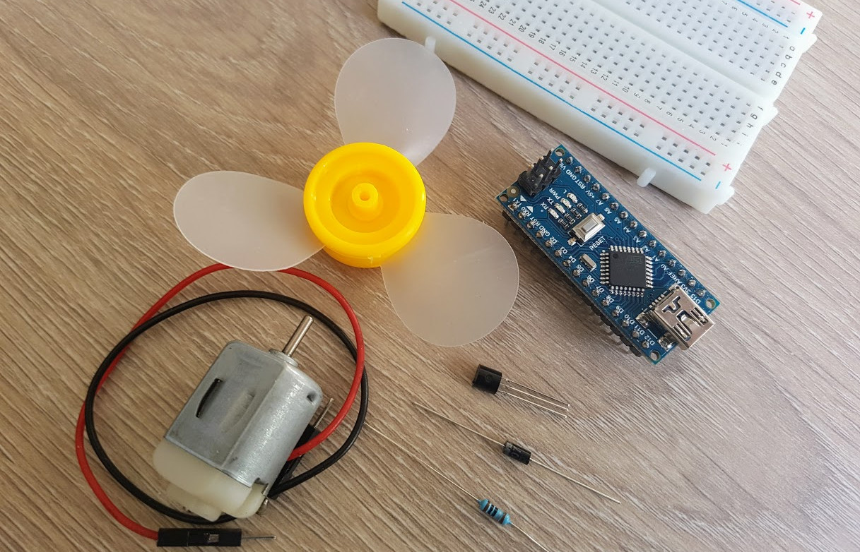
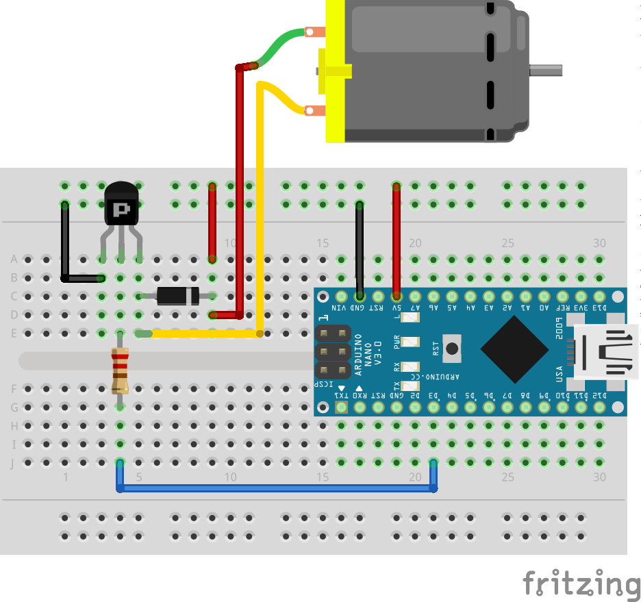
Building the physical fan
Our fan is just a simple DC motor, so we will use the following components:
- DC motor
- PN2222 transistor
- 1N4007 diode
- 220Ω resistor
Let’s connect everything together and test it:
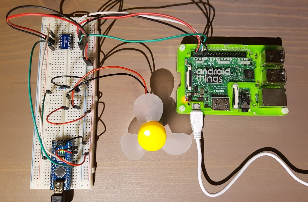
Connecting the Arduino to the Android Things board
Ok, it works.
To connect now the Arduino to the Android Things board via I²C, we simply need to connect the SDA, SCL, GND pins of the Android Things board and the Arduino together.
Careful: If your Android Things board is a 3.3V device (such as the Raspberry Pi 3 or NXP Picos boards), you will need a bi-directional level shifter for the I²C bus, so that inputs from the 5V Arduino won’t damage your board.

Source code
You can find the complete source code on GitHub:
https://github.com/Nilhcem/i2cfun-androidthings/tree/arduino_slave
In the following article, we will re-use this homemade device to demonstrate how we can connect multiple I²C devices to the same bus.