Android Things - Discovering the I²C API creating a capacitive sensor driver
Attention please: if you are not in the mood to read so much content, but just want to watch a fun video, scroll down to the bottom of the page.
Physical buttons are nice, but sometimes, you may want to include capacitive buttons instead in your Android Things projects.
An easy way to get started with touch sensors is to play with the MPR121:
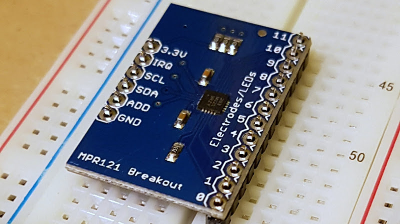
This component offers 12 different capacitive channels. Connect up to 12 wires and be notified each time the MPR121 detects a capacitive touch on any of these wires.
You only need 4 wires to plug it onto the Android Things board: one for the voltage (3.3V), one for the ground (GND), and 2 cables for the SCL and SDA.
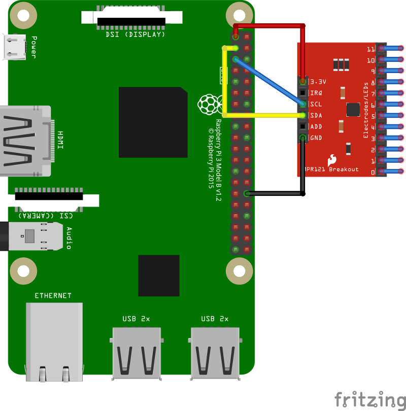
SCL? SDA?
The MPR121 is communicating with the board via I²C (Inter-Integrated Circuit).
I2C, pronounced I, squared, C, is a serial bus useful to connect peripheral devices with small data payloads.
All data is transferred over one wire named SDA, (Serial DAta Line). It requires another wire: SCL (Serial Clock Line) to coordinate data exchanges between the connected components.
Another nice thing with I²C: you can plug, if you want, multiple slaves on the SDA / SCL wires, so that a master (e.g. our Raspberry Pi) can send data to multiple peripherals at once. We won’t use this feature today, but feel free to check the Android Things official I²C documentation for detailed information.
Step 1: Import the Android Things driver
The first thing to do, when you want to play with capacitive touch sensors, is to create a new Android Things project, and import the capacitive sensor driver.
Well… there is a capacitive sensor driver (CAP12XX) for Android Things, but no MPR121 driver available yet.
Beginner’s mistake… Driver is not compatible with this hardware.
Step 0: Create the MPR121 driver
Since there are no MPR121 drivers yet, why not create our own?
Writing one from scratch may look complicated, especially when we are the kind of people who make beginners’ mistakes.
But porting an existing driver to Android Things is a much easier task. Lucky us, there’s already an Arduino driver from Adafruit. Let’s see its content:
First, setting up the MPR121
To be able to detect capacitive touches, the MPR121 needs some setup. Below is a sample of the Arduino library code:
// The MPR121 I2C default address is at 0x5A
uint8_t I2C_ADDRESS = 0x5A;

// Setup method
boolean Adafruit_MPR121::begin(uint8_t i2caddr) {
    // Wire is an Arduino library that allows I2C communication
    Wire.begin();

    // A lot of stuff I don't understand, but it looks important
    writeRegister(0x80, 0x63);
    writeRegister(0x5E, 0x00);
    writeRegister(0x2C, 0x01);
    writeRegister(0x2D, 0x0E);
    writeRegister(0x2E, 0x00);
}

// writeRegister is actually a way to write an 8-bit value at a given address
void Adafruit_MPR121::writeRegister(uint8_t reg, uint8_t value) {
    Wire.beginTransmission(I2C_ADDRESS);
    Wire.write((uint8_t)reg);
    Wire.write((uint8_t)(value));
    Wire.endTransmission();
}
We can see that we need to interact with registers. Specifically, writing multiple register values to initialize the component.
Good news for us, Android Things Peripheral I/O provides a writeRegByte(address, value) method to let us write an 8-bit value to a register address.
Here’s the same code, translated for Android Things:
// The MPR121 I2C default address
int I2C_ADDRESS = 0x5A;

// First, we get a reference to our I2C device, connected on "I2C1"
PeripheralManager manager = PeripheralManager.getInstance();
I2cDevice device = manager.openI2cDevice("I2C1", I2C_ADDRESS);

// Then, we write all the "important-but-I-don't-really-get-it-yet" stuff
device.writeRegByte(0x80, (byte) 0x63);
device.writeRegByte(0x5E, (byte) 0x00);
device.writeRegByte(0x2C, (byte) 0x01);
device.writeRegByte(0x2D, (byte) 0x0E);
device.writeRegByte(0x2E, (byte) 0x00);
Then, getting sensor data
The setup is done.
Remember, the MPR121 is a component that can give us the state of 12 different sensors.
If a sensor is pressed, the value will be 1, if not, the value will be 0.
The MPR121 returns an int that corresponds, in its binary form, to the value of every of these sensors, one for each bit.
For example, a value of 0x42 (binary: 0b000001000010) would mean that sensors number 2 and 7 are touched.
Here is the Arduino code, to get the value of all of these sensors:
uint16_t Adafruit_MPR121::getSensorsStates(void) {
    uint16_t t = readRegister16(0x00);
    return t & 0x0FFF;
}
This time, the method readRegister16 reads the value on a 16-bit-integer at address 0x00.
There’s a binary AND operation to ensure we only get values for the 12 sensors. (0x0FFF is equal to 0b0000111111111111 in binary). Don’t count, there are twelve 1. Because there are twelve sensors.
Once again, there’s a similar I²C method for Android Things: readRegWord(address) which reads a 16-bit-value at a given address.
The similar code, written in Java would be:
public int getSensorsStates() {
   return device.readRegWord(0x00) & 0x0FFF;
}
And then, to simplify, we can convert it to a boolean array of 12 values, one for each sensor (true for touched, false otherwise):
boolean[] toBooleanArray(int sensorsStates) {
  boolean[] array = new boolean[12];
  for (int i = 0; i < array.length; i++) {
      array[i] = isBitSet(sensorsStates, i);
  }
  return array;
}

boolean isBitSet(byte value, int bitIndex) {
    return (value & (1 << bitIndex)) != 0;
}
And we are (already!) done. Our very simple driver is created.
Step 2: Do something fun with the MPR121
Now, we can use it to do something cool.
I decided to connect 12 drink cans to the MPR121, an external speaker to the Raspberry Pi, and use Android’s SoundPool (since API 1, #LOL) to play a sound when any of the cans are touched.
Here’s a video of my (let’s find a name.. ahem…) “Android Things Daft Punk Beer Can Sound Box”, in action:
MPR121 driver and sample project on github.com/nilhcem/mpr121-androidthings.
Conclusion
Interacting with I²C is all about reading and writing values on registers.
It might look scary at first, but it’s as easy as reading and writing into an array.
Here are all the methods you need to know, to play with I²C:
readRegByte()andwriteRegByte()read or write an 8-bit register value.readRegWord()andwriteRegWord()read or write a 16-bit register value.readRegBuffer()andwriteRegBuffer()read or write up to 32 consecutive register values as an array.
You also have some read() and write() methods to transfer raw data.
More information, once again, on the official documentation.
PS: If you need a personal DJ for any type of events, buy me a few cans of beer, and a Raspberry Pi. I’m coming right away.