Android Things - Discovering the GPIO API through building a remote car
@riggaroo @blundell_apps 2017 will be the year of blinking leds powered by Android.
— Hugo Visser (@botteaap) December 18, 2016
When the first developer preview of Android Things was released in December 2016, my twitter timeline was flooded with pictures of lonely LEDs, blinking on top of large breadboards. And of course, I contributed too.
The truth is that for many of us, Android developers, having the possibility to interact with physical objects is something completely new.
We have been creating software for years. Polished applications used by millions of users is not something that impresses us so easily, but succeeding in blinking an LED is a different matter.
And, let’s be honest, using RxJava + Kotlin to blink an LED is surely some over-engineering stuff, but it makes us feel like we are coming from the future with our advanced tools to interact with things almost a century older. #SoMuchPowerInOurHands
How to blink an LED?
Blinking an LED is a necessary first step if you want to discover Android Things.
If you haven’t reached this stage yet, take a look at the official blinking led sample, or any other detailed tutorial, available on the Internet and find some time to do those. You’ll learn, and it’s fun.
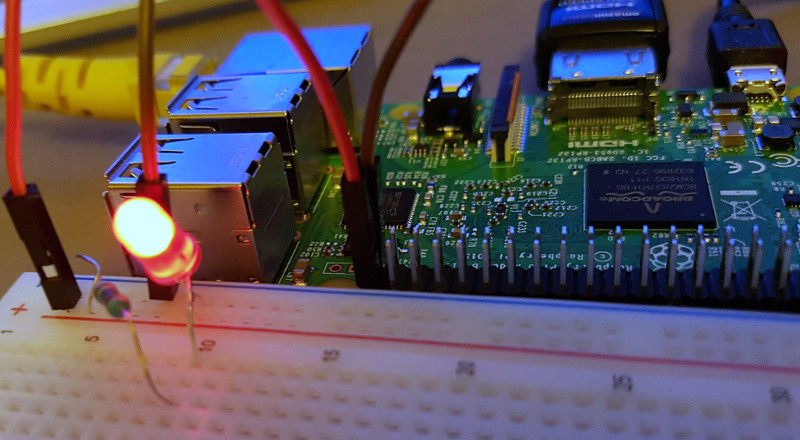
In a nutshell, turning an LED on is simply telling the board (e.g. the Raspberry Pi) that it should supply some current to it (but not too much, that’s why we use a resistor to limit the current that flows through the LED).
And to translate this action into code, Android Things provides a GPIO API.
At that moment, any boring tutorial would tell you that GPIO stands for General Purpose Input/Output, but who cares? To simplify, it’s a very simple way to start sending, or stop sending current to a peripheral.
Understanding this API is the easiest and essential way to get started with Android Things.
// First, we ask the PeripheralManager to give us a reference of our LED
// We have connected our LED to the Raspberry Pi GPIO pin named "BCM21"
// The LED is an output device. It receives orders from the board.
Gpio ledGpio = PeripheralManager.getInstance().openGpio("BCM21");
ledGpio.setDirection(Gpio.DIRECTION_OUT_INITIALLY_LOW);

// To turn the LED on, we set the value to true
ledGpio.setValue(true);

// To turn the LED off, we set its value to false
ledGpio.setValue(false);

// Alternatively, we can also get the LED value
boolean isOn = ledGpio.getValue();

// And we close the peripheral, because we are good guys
ledGpio.close();
As you can see, blinking an LED is as easy as setting a boolean value from false to true, and vice versa.
#ThatSimple
From blinking an LED to building a remote toy car in the same blog post? Are you even serious?
Now you know how to turn an LED on and off via the GPIO API, you can create a remote car! Seriously! Before explaining the similarities between an LED and a car with 2 DC motors, let’s buy some fun stuff
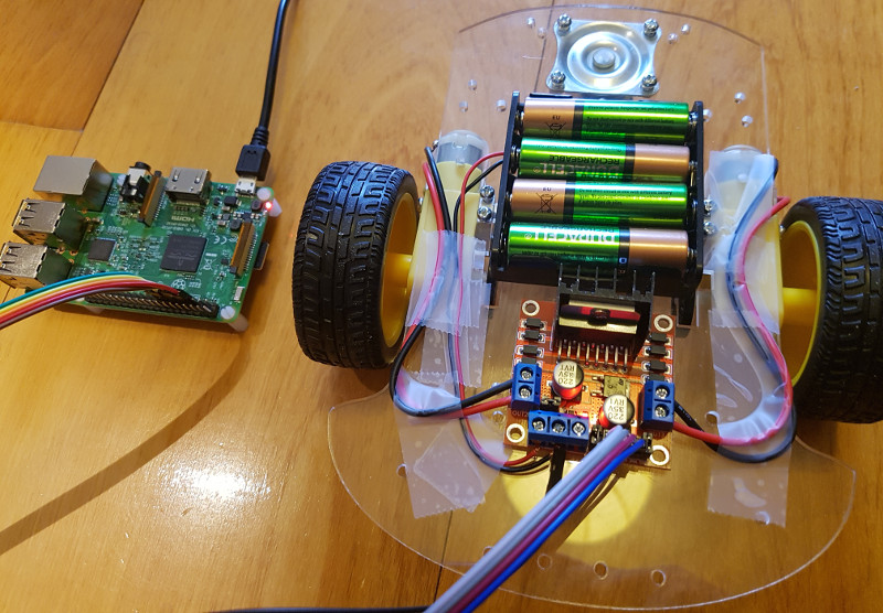
Buying a Car Chassis Kit
If I were a smart guy, I would probably buy the components separately, but (warning: excuse incoming) like every good developer, I’m a bit lazy and decided to buy a Car Kit Chassis, which contains 2 gear motors with car tires, a battery box, a universal wheel and a few wires.
Below, a picture of the Mohoo Kit Chassis I bought on Amazon for $15
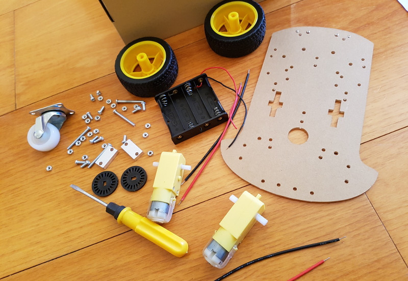
The battery box is necessary, as the Raspberry Pi power is not enough to get the motors working properly.
But keep in mind the battery box will be only for the motors. You will need an external power source for the Raspberry Pi (I decided to use a portable power bank)
20 minutes later
Buying an L298N dual motor controller
The chassis kit by itself is not enough to have a functionning car, we need to buy the last component separately: an L298N H-Bridge motor controller. I found mine for $2 on aliexpress.
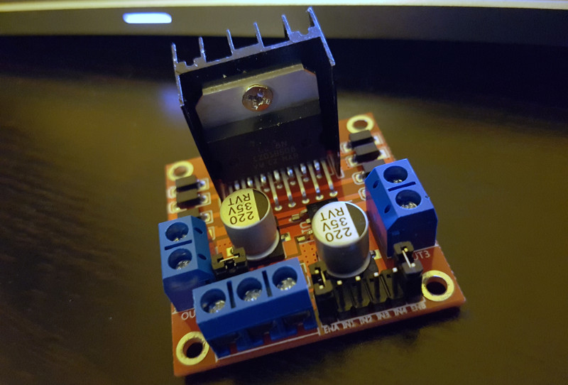
The L298N is a great component that allows us to control the speed and direction of two DC motors.
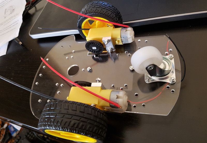
Plugging the wires
We will plug the 2 wires of each DC motors to each sides of the L298N. We’ll also plug the 2 wires of the battery box at the front of the L298N controller (Ground and [up to] +12V).
Finally, we connect the L298N controller to the Raspberry Pi using 5 wires. 1 ground and 4 GPIOs
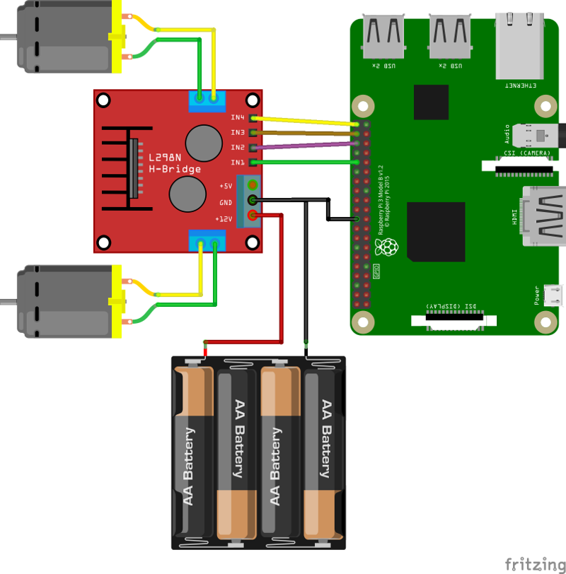
It is important that both the battery pack ground wire and the Raspberry Pi ground wire are connected to the same L298N ground pin
The magic of the L298N is that the component will simplify the communication with the DC motors.
As you can see, it is connected to 4 GPIO pins on the Rasperry Pi.
- GPIO1: Move the left wheel forward
- GPIO2: Move the left wheel backward
- GPIO3: Move the right wheel forward
- GPIO4: Move the right wheel backward.
And since you now already know how to turn on and off an LED. You know how to supply current to each of these GPIOs:
switch (direction) {
  case FORWARD:
    gpio1.setValue(true);
    gpio3.setValue(true);
    break;
  case BACKWARD:
    gpio2.setValue(true);
    gpio4.setValue(true);
    break;
  case LEFT:
    gpio3.setValue(true);
    break;
  case RIGHT:
    gpio1.setValue(true);
    break;
}
Moving a toy car is as easy as turning 2 LEDs on at the same time.
Why would you need Android Things for that?
You don’t. Interacting via GPIO can be done in many ways.
But let’s say you want to improve this project further:
First, you will want to control the car from your iPhone or Android device. Later, you may want to transform this car into a robot that can take pictures, upload them to the Cloud and use the Cloud Vision API for image content analysis.
Here, Android Things will be useful, because you will be able to write your code very quickly, as you already know how to develop Android applications. And you will be able to interact with Google APIs for all your needs.
Control the car from your phone
To create a wireless connection between my phone and the car, I decided to use the Nearby Connections API over Wi-Fi. As I was already familiar with the API. It only took me 20 minutes to integrate it and create a(n ugly) Android app.
If you are not familiar with the Nearby Connections API, I recommend you to read the official documentation
I also suggest you to take a look at Rebecca’s great distributed Android Things piano to better understand this part and build something similar.
Result
You can see below a video of the car in action:
As a conclusion, the gap between turning an LED on, and succeeding in moving a two-DC motor-car is not as large as we might think. Technically simple, but the result looks pretty impressive!
The GPIO API is a great way to get started with Android Things.
Now, your turn. Have fun!